
Barkell Bespoke Range
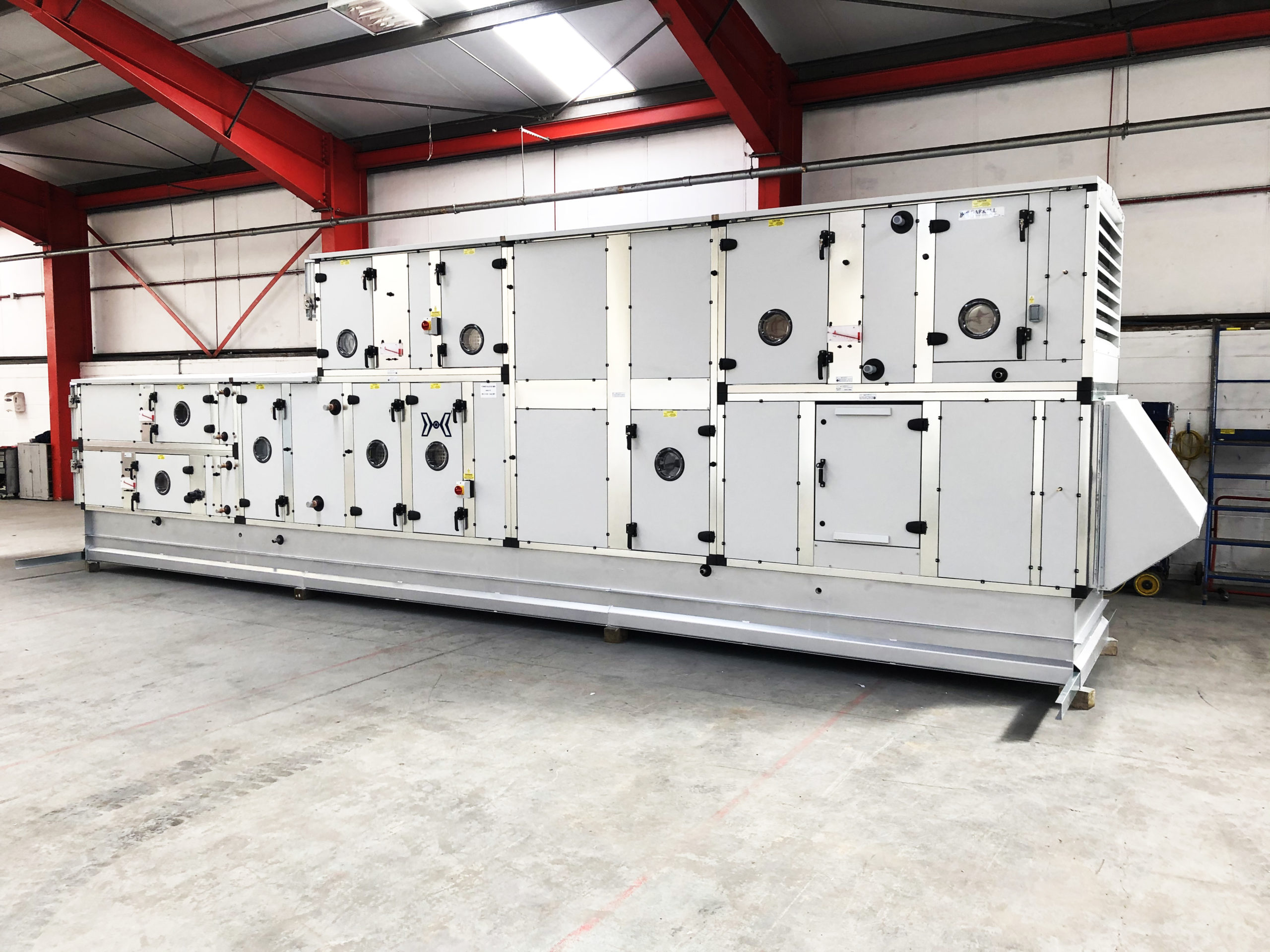
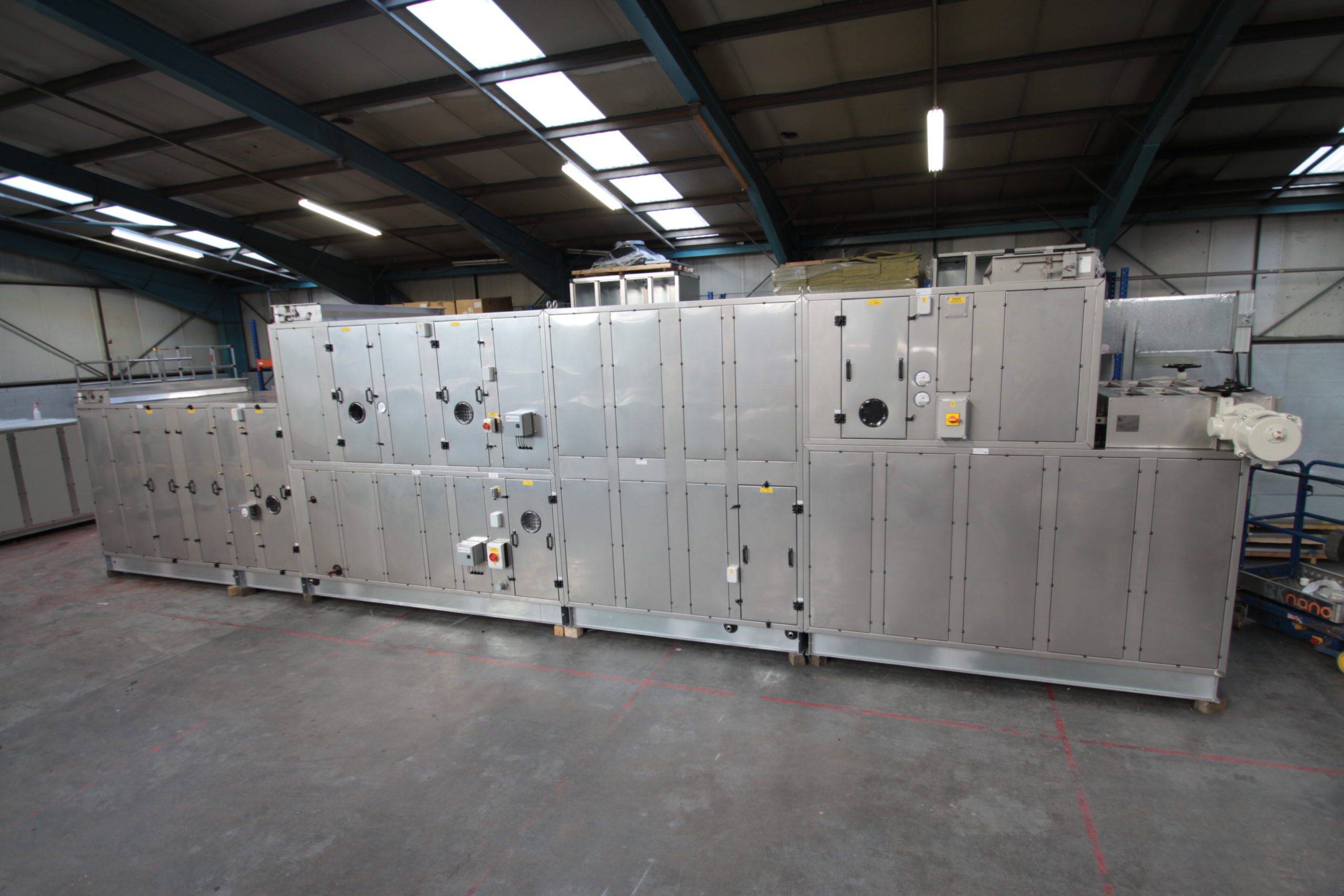
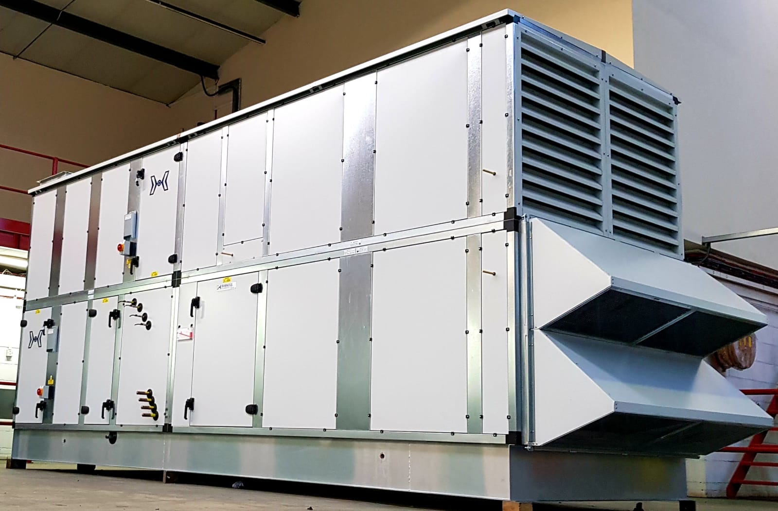
Air Handling Units
0.2m3/s to 50m3/s
Our air handling units (AHU) are delivered in various case sizes with airflow from 0.2m³/s to 50m³/s. We operate with a ‘less-is-more’ ideology and always strive to manufacture the most compact air handling unit we can given the required design parameters. This makes them ideal for indoor installation (internal installation) and for outdoor applications (external installation) where space is tight and of paramount importance.
Airedale can also support existing air handling unit installations with a complete AHU upgrade and refurbishment service, plus comprehensive maintenance options. Contact our specialist AHU team in the tabs below for more information.
What types of air handling units do we offer?
We deliver a varied and diverse range of Air Handling Units (AHU) developed to meet your specific needs. The below will give you a flavour of the types of air handling units that we can offer you.
Our air handling units are delivered in various case sizes with airflow from 0.2m³/s to 50m³/s. As you would expect, the larger the flow rate required, the larger the case size but we always aim to deliver maximum system output from the smallest possible footprint whilst providing adequate space for maintenance.
We operate with a ‘less-is-more’ ideology and always strive to manufacture the most compact AHU we can given the required design parameters. This makes them ideal for indoor installation (internal installation) and for outdoor applications (external installation) where space is tight and of paramount importance.
- Unit constructed to meet the leakage requirements of BS1886 leakage class L2 (DW143 class B).
- Frame to be vapour sealed.
- Fan motors wired to local isolators.
- Fan assemblies mounted on vibration isolators.
- Fan assemblies earth bonded.
- Fan discharges fitted with internal flexible duct connectors.
- Post work insulated around and downstream of cooling coils.
- Coils installed on slide rails.
- Drain trays manufactured to eliminate ponding and extended beyond the component casing to allow inspection and cleaning.
- Panel and bag filters fitted with inclined manometers, HEPA filters with vertical manometers.
- Bag filters installed in frames with pockets in vertical orientation.
- Man access sections fitted with reinforced floor panels.
- Air inlet and outlets suitable for flanged duct connection.
- All units fitted with flush base skids.
- All sections fitted with permanent lifting facility.
- Access doors adjustable to allow for seal deterioration.
- All non-access enclosure panels removable.
- All unit sections and components fitted with identification and warning labels.
- Finish: Framework; self-finish galvanised
Panels; plastisol coated
Optional Extras (non-exhaustive)
- Unit constructed to meet the leakage requirements of BS1886 leakage class L1 (DW143 Class C) or to exceed BS1886 leakage class L1 (DW143 Class D).
- Fan motors wired to local isolators complete with auxiliary contacts.
- Drive guards shall be fitted to all fan assemblies.
- View glasses shall be fitted to all fan sections.
- View glasses shall be fitted to all access sections.
- View glasses shall be fitted to all humidifier sections.
- Unit access areas fitted with bulkhead lights, pre wired to external switches.
- Fan sections fitted with bulkhead lights, pre wired to external switches.
- Humidifier sections fitted with bulkhead lights, pre wired to external switches.
- Test points shall be fitted between all components.
- All access doors shall be key lockable.
- The unit shall be fitted with guttering, down comers and shoe discharges.
- Barkell Limited shall attend site to complete assembly, following final positioning by others.
- The units shall be leakage tested at works.
- The units shall be witness leakage tested at works.
- The units shall be leakage tested on site.
- Non-standard colours available.
- Floating hinges for low leakage applications.
- Integral trunking within the AHU frame work.
- Integral enclosures can be provided for controls or power distribution equipment.
- A comprehensive controls package can be supplied for each AHU.
AHU components / options
-
Belt drive fan section with optional run and standby facility or motors external to the air stream
-
Direct drive fan section (plenum or centrifugal type, EC or high efficiency AC, PM motor option)
-
Maintenance access, air diffusion space, turning plenums
-
Attenuation
-
Particulate filtration (panel, bag, rigid)
-
Carbon filtration for odours and contaminants
-
High efficiency particulate air filter
-
Heating coil (water/steam)
-
Cooling coil (water/DX gas)
-
Electric heater
-
Indirect and direct gas heater
-
Steam humidifier (direct steam or self-generating – electrode boiler, resistive, gas)
-
Modulating or shut off damper
-
Mixing/exhaust box
-
Plate heat exchanger (with or without bypass for free cooling) can be aluminium, coated aluminium, plastic, etc.
-
Thermal wheel (sensible, hygroscopic, desiccant, enthalpy)
-
Units with internal corridors
-
Run around coils
-
Inlet/Outlet with ducted connection/louvre/hood/acoustic louvre
-
Adiabatic cooling or humidification
-
Integrated controls
-
N+1 redundancy
-
Acoustically and thermally insulated casing as standard, with further acoustic and thermal options
-
Fully welded galvanised steel box section frame work as standard, stainless steel and aluminium options
-
Interior lighting and viewing options
-
Raised or specially designed base frame options
-
Fixed (but accessible) or removable drain tray options in galvanised or stainless steel
-
Non standard colours available
-
Pitched roof as standard on externally mounted air handling units
-
Integrated air to air heat pump for cooling or reverse cycle operation
-
Fully packaged ‘plug and play’ option
AHU design – UK designed and manufactured
Our range of experienced, air handling unit engineers will work in partnership with you to ensure that we design a unit to meet and exceed your exact specification. Each AHU arrangement and component selection is individually designed to your specific requirement ensuring the air handling unit produced performs with peak performance and optimised efficiency.
Our AHU design process
Upon submission of your air handling unit requirements, either to our experienced technical sales engineers (who cover the length and breadth of the UK) or direct in to head office, initial design, at tender stage, is carried out by our experienced team of estimators and application engineers.
At this point, your project will be discussed in full and proposals will be based upon required flow rates (0.2 m³/s to +50m³/s), volumes, application, unit specification and limiting factors of the project (i.e. site access, unit size, unit configuration – side-by-side / stacked).
Once your order is placed, the air handling unit project is passed to our contracts department, where initial designs are adjusted, calibrated and finalised by our highly experienced engineers.
AHU unit arrangement CAD drawings are then put into production and can be supported by Computational Fluid Dynamics (CFD) – this service is optional and chargeable. Following this process, technical and performance documentation plus drawings are submitted to you for finalised sign-off. Once approved, drawings are issued to production and units are manufactured, 100% in the UK.
At every stage of the tender, throughout design and manufacture, we will strive to work with you to ensure we adhere to your specification. Indoor air quality is paramount to every AHU unit that we manufacture. Within our units we strive to provide crevice free internal surfaces to assist in maintenance.
BIM models are also available on request
Our bespoke air handling unit team can work with your engineering consultants to develop a product to match your specification. Working with you, we can advise, design and develop an AHU that meets the needs of your project.
There are some standard elements of design that we advise upon, some of which we have referenced below.
Design
Typically, air handling equipment is designed for horizontal or vertical air flow, with units matching internal width and height to ensure smooth efficient air movement through each section of plant with minimum turbulence and pressure loss.
Construction
The unit framework is typically constructed using 50mm penta box section, manufactured from 18 swg (1.2mm) Z2 hot dip galvanised steel and has a natural galvanised finish.
The frame is assembled using pre-formed corner sections and is seam welded internally; intermediate post work is fitted where necessary to provide a structure of strength and rigidity. The frame has to be capable of supporting the components and fittings forming the air handling unit and withstanding the pressure within the air system under operating conditions. The frame is vapour sealed.
All post work around and downstream of cooling coils and other drain tray sections is fully insulated throughout their entire length. The insulation material has the same acoustic and thermal properties as that identified for cladding panels elsewhere in the specification.
All strength is provided by the permanent framework and does not rely on the cladding panels.
All air inlet and outlets shall be suitable for flanged duct connection.
Enclosure and access Panels
All enclosure panels and access doors are typically a nominal 45mm deep and double skinned. The outer skin is manufactured from 20 swg (0.9mm) B.S.C. colour coat plastisol (plastic coated steel). The standard colour shall be Goosewing Grey (BS 10A05). The inner panel skin is manufactured from 22 swg (0.7mm) Z2 hot dip galvanised steel. The cavity is packed with slab rockwool insulation, with a density of 45kg/m³ (thermal conductivity of 0.035 W/mK), compressed between the inner and outer skins, to form a panel with excellent thermal and acoustic properties. On units large enough for internal access, the floor panels have reinforced insulation to facilitate maintenance access.
Internal floor panels are to be welded in place. All other panels are flush mounted into the unit frame and are fully removable.
All panels are located on closed cell neoprene acoustic gaskets, about their perimeter.
Unit base skid
All air handling units are fitted with a steel base, fabricated from galvanized steel, designed to support the unit at the relevant structural points.
Leakage testing
As a minimum the AHU is constructed to meet the leakage requirements of DW143 class B (BS1886 leakage class L2). We can construct units to other requirements on request.
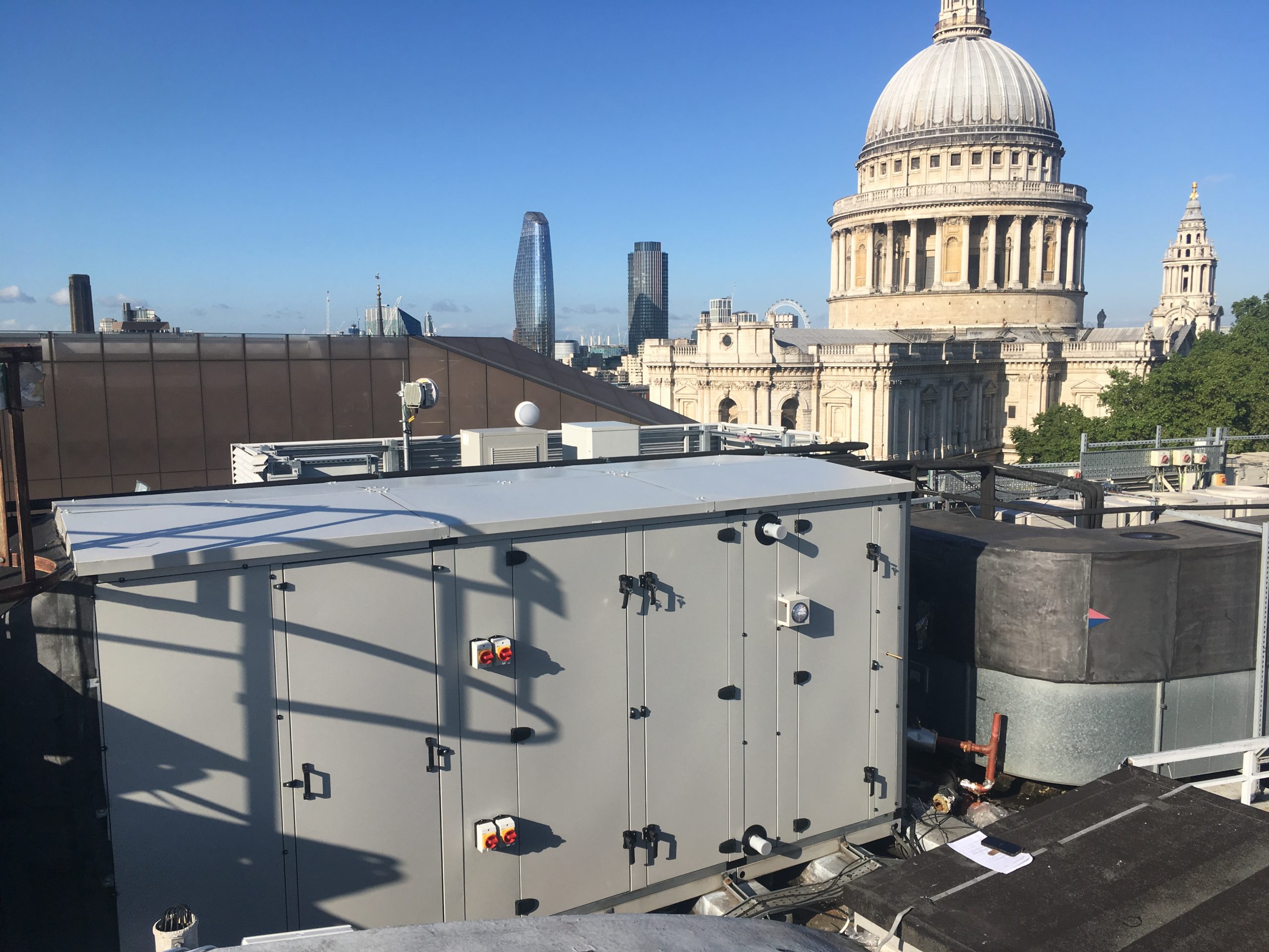
Weather protection
When units are to be installed externally, they can be provided with a trussed pitched roof fitted over all elements of the framework.
The roof is manufactured from 0.7mm Z2 hot dip galvanised steel with a finish to match the AHU frame work and is flashed and sealed where jointing is necessary to prevent water ingress.
All unducted fresh air intakes and exhaust air discharges are fitted with either weather hoods or louvres complete with a bird/vermin screen.
Service and Maintenance
Access needs to be provided to each section of plant for inspection and maintenance purposes. Access doors are provided to areas of regular maintenance; door furniture is either hinged or lift off operation.
Units need to be constructed to eliminate the transmission of mechanical vibration.
All units feature identification, airflow and warning labels.
Delivery and Installation
For ease of handling, larger units can be transported in sections for on-site assembly. All jointing gaskets, sealing materials and hardware is provided to allow assembly to be completed.
Suitable permanent lifting points need to be incorporated into the unit base frame or framework.
AHU configuration
Our AHU selection guide enables you to rapidly select the appropriate unit size for a specific project requirement.
Simply, select the velocity and volume (or next highest value) required from the table. Then, locate the unit size, external width and external height from the left hand column. Finally, add the base height to the external unit height and 50mm for a pitched roof if the unit will be sited in an external location.
Please note that dimensional restrictions may dictate a higher velocity of around 3m³/s. This, however, is likely to mean that the AHU specific fan power will exceed Building Regulations requirements. Subject to external static pressure and internal components, Building Regulations requirements may be met at an AHU velocity of 2m³/s.
AHU sizing calculation guide (matrix below as a .pdf file)
Approximate Length of Air Handling Unit Components for Unit Size (.pdf)
Approximate Weight of Air Handling Unit Components for Unit Size (.pdf)